If you have a background in coding, you’ll probably be familiar with UML diagrams. Why? Because typically, software developers use UML diagrams to create new systems. But in today’s world, they’re not limited to a single capacity. In fact, UML diagrams are used widely across different areas of business.
So whether you’re a business manager or a software developer, an understanding of UML diagrams can go a long way. It’s always helpful to refresh your memory and familiarize yourself with the best practices for UML diagramming.
In this article, we’ll outline what UML is, how to use a UML diagram, and the different types of UML diagrams out there.
Why was UML developed?
Unified Modeling Language (UML) is a standardized modeling language. It helps software developers visualize, construct, and document new software systems and blueprints.
UML is used to create static structure diagrams based on a variety of engineering practices that have proven to be successful in the creation of complex systems. The published standards are almost 800 pages long.
Historically, UML has been used to model software systems, but it’s not limited to software developers. Today, UML diagrams are also used to manage processes and projects. In this scenario, UML diagrams outline entire workflows and business processes.
UML was created in 1995 by Grady Booch, Ivar Jacobson, and James Rumbaugh. In 1997, the Object Management Group adopted UML, meaning it was rolled out to companies such as Hewlett-Packard, Apple, and IBM.
In 2005, the International Organization for Standardization (ISO) standardized it. It’s constantly been reviewed and revised since then, with the latest UML specification taking place in 2015.

UML was created as a clear modeling language for developers to use. It was designed to be simple and easy to understand so that everyone could follow the process and design of the software.
Today, it’s not just used by software developers. It’s a more widely used approach to application structures and modeling, as well as documenting software.
What is a UML diagram?
For software developers, keeping on top of hierarchies and relationships within a system can be difficult — especially when focusing on complex and detailed areas of code.
But using a UML model divides these systems into components and subcomponents. This makes it easier to visualize, plan, and execute their project.
For business analysts, a UML diagram helps them visualize the system or process they’re working on.
When it comes to creating a UML diagram, a lot of businesses use a UML diagram template.

Using a ready-made template saves time and allows you to create a UML diagram as quickly and efficiently as possible.
When should you use a UML diagram?
Most commonly, a UML diagram is used to analyze existing software, model new software, and plan software development and prioritization. Simply put, if you need a way to visualize and plan your software development process, a UML diagram is incredibly helpful.
For business management, a UML diagram helps teams organize their workplace, create process documentation, and streamline their workflow.
They can also be used to update stakeholders on business operations and progress. And if you’re using a collaborative platform, you can easily invite external collaborators and stakeholders to view the diagram.
The benefits of using a UML diagram
Now that we know what a UML diagram is and what it’s used for, let’s take a look at some of the benefits of using it.
Keep everyone on the same page
UML is a standardized language. Every UML element means the same thing no matter what business is using them and what the diagram is for.
For example, the ‘actor’ icon represents a user. This could be a customer, someone on the internal team, or another system that interacts with the subject of the diagram (in this case, it would be your software).
This icon is always presented as a stick figure. Whenever anyone sees this icon, they’ll automatically know what it means in the context of your diagram.

So when it comes to creating a UML diagram, the standardized symbols make it easier for everyone to understand the diagram. There’s no confusion about what certain icons mean, and everyone knows how to read a UML diagram effectively.
Explore different options
Rolling out new software or updating an existing one can be a costly and time-consuming process. For this reason, it’s not always possible to test different versions of the software to see what works best.
This is where a UML diagram can help.
Before you launch the new software, you can use the diagram to test out different structures. As a result, you can make changes and improvements before launching the software. This saves you both time and money in the long run.
Have clear documentation of workflow
By using a UML diagram, you’re able to document your new software or business processes. This means you can track progress over time, make sure things are going to plan, and identify key areas of improvement.
Let’s say you’ve used a UML diagram to plan a new business process. The process has been rolled out to your team, and they’re following the new steps.
But something isn’t quite right. The process isn’t moving your workflow along as quickly as you’d hoped. To identify what’s causing the holdup, you refer back to your UML diagram and pinpoint the root of the problem. And once you’ve found the issue, you can put things right.
Most commonly used UML diagrams
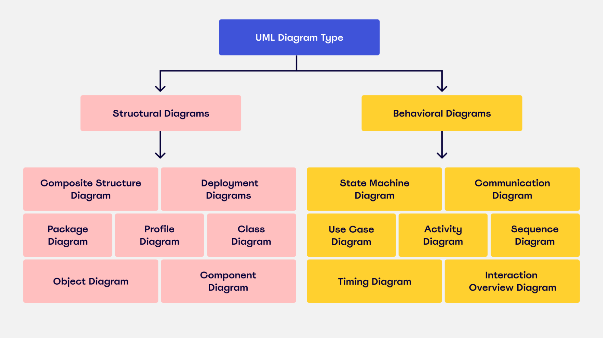
There are various types of UML diagrams that are used for different software structures. There are 14 official types, with some additional versions that aren’t officially recognized but are widely used.
The diagrams are split into two different categories: structural diagrams and behavioral diagrams.
A structure diagram shows how a system is constructed. This includes components, classes, objects, and how all of these elements connect. Behavior diagrams visualize how a system interacts with itself, users, and other systems.
Here’s a breakdown of the different types of UML diagrams and whether they’re classified as a structural diagram or behavioral diagram:

Now, let’s take a look at some of the most commonly used UML diagrams in more detail.
Class diagram
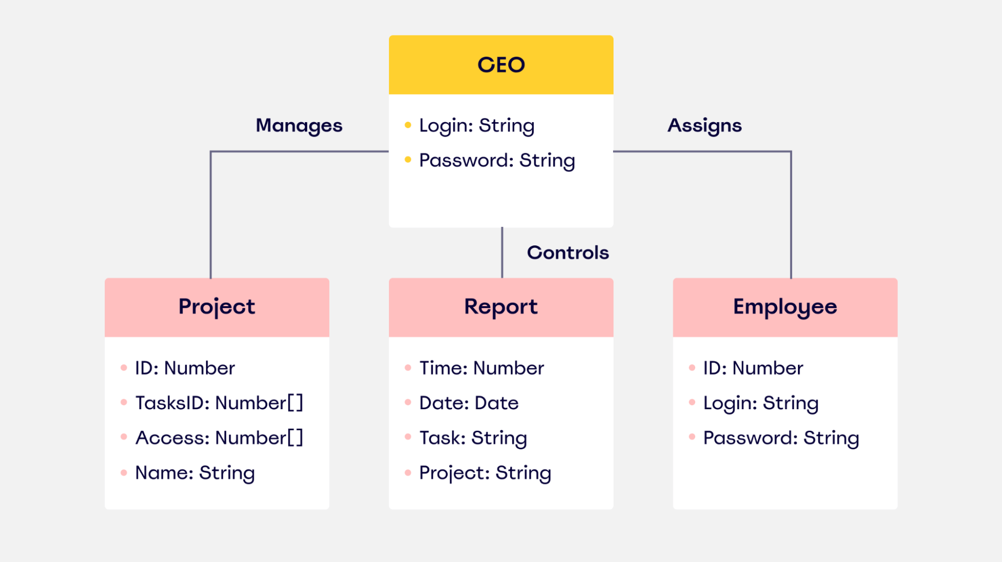
A class diagram allows you to map the structures of a system displaying various classes, attributes, operations, and relationships between objects. Both software engineers and business managers use this interaction diagram to model different connections involved within a process.
In the diagram, the class is represented with a rectangle. Each rectangle is split vertically into three sections. The top section has the name of the class. The second and third sections provide details about class operations, behaviors, and attributes.

Because software is typically based on object-specific programming, a class diagram is probably the most commonly-used UML diagram.
Component diagram
A component diagram breaks down a complex system into smaller components, making it easier to visualize. Unlike other UML diagrams, it specifically outlines the relationship between these components.
Take a look at this example of a component diagram for a library management system:

You can see from the diagram that the main focus lies with how and where the different objects are connected.
Visually speaking, it’s pretty similar to a class diagram. It has the same notation rules, but it’s more specialized and tailored to a complex system.
Use case diagram
Use case diagrams show interactions between users — also known as ‘actors’ and represented as stick figures — and the system itself.
It illustrates system functionality, focusing on the expected behavior of the system and showing what will happen and when.

A use case diagram is often used as a top-level overview of how users and systems interact. As a result, it’s a useful way for a non-technical audience — which can include key stakeholders — to visualize your system.
Activity diagram
An activity diagram is a flowchart that outlines all the activities performed by a system.
It shows everything from start to finish, defining the various decision paths and steps that need to happen to move from one activity to the next. The steps can be chronological, branched, or simultaneous.

This diagram is commonly used to manage the internal structure of business processes. It allows business analysts to effectively plot and manage various workflows in one location.
Deployment diagram
Deployment diagrams show the configuration of processing nodes, as well as all the components that live on them.
In other words, they show how software runs on components within a system. It helps users model the physical aspects of object-oriented software.
These diagrams are mostly used by system engineers. By using this diagram, they can keep track of their entire hardware mesh and prepare the system for launch without any issues. It also allows them to see performance, maintainability, and scalability.
Sequence diagram
Sequence diagrams — sometimes known as event diagrams — show the order in which your objects interact. This includes the lifelines of your objects, the processes that interact with your objects, and the messages exchanged between the objects to perform a function.
These diagrams are often used by developers and business professionals to understand how to structure a new system or improve an existing process.
Take a look at this example of a UML sequence diagram for an ATM machine:

As you can see from this image, the sequence diagram outlines all the steps that interact with the ATM machine and the user. It covers all the possible actions the user can take and shows how the ATM machine will respond in each situation.
Object diagram
Object diagrams show the attributes of each object in a system and how those objects relate to one another at a specific time.
Take a look at this example of an object diagram for the use of a bank account:

The diagram shows the current state and attributes of the objects (the bank accounts) at this particular stage. It shows what actions the user can perform and the class limitations they have in place.
Object diagrams like this are often used alongside class diagrams. Why? Because an object diagram tends to represent a certain part of a class diagram.
In this situation, a class diagram would illustrate the entire baking system. An object diagram will focus on the use of different objects throughout the system. This helps you verify the effectiveness of your class diagram.
Package diagram
As the name suggests, a package diagram is used to show the dependencies and relationships between packages in a system. A package refers to anything that organizes any model element. In the diagram itself, it’s presented as a file folder.
The package diagram allows the user to group items into folders. Items that can be grouped include classes, use cases, documents, diagrams, and even other packages. Once each item is allocated to a package, all of the packages are then arranged and ranked hierarchically in the diagram.
These diagrams are mostly used to visualize software systems because they easily portray the top-level structure.
Best practices for creating a UML diagram
Now that you know about the different types, you’re probably wondering how to make a UML diagram.
While the process of creating one differs greatly depending on your business needs, we’ll outline a couple of the best practices you can follow.
Choose the right UML diagram type
We already know there are multiple versions of UML diagrams. So before you do anything else, you need to know what type of UML diagram you need.
To figure out which diagram is right for you, here’s what you need to do:
- Understand the different types of diagrams: To know which of the structure diagrams is right for your requirements, you need to fully understand the different types. This article is a great starting point, but there are other diagrams we haven’t covered. There are 14 official diagrams. Do some more research to give yourself a thorough understanding of what UML diagrams are available.
- Identify why you’re creating the diagram in the first place: Do you know what you want to learn from your diagram? Or why you need one in the first place? Or who you’ll be sharing it with? All of these questions need to be answered before you start your diagram. Without this information, it’ll be hard to choose a diagram that’s best suited to your needs.
Find the right software
Once you’ve done some additional research and figured out which type of UML diagram is right for you, you now need to find the right UML tool to create it.
There’s a lot of software out there to choose from, which can be pretty overwhelming if you’re new to UML diagrams.
To make the search easier and help you find the right modeling tool, here are some of the features we’d suggest looking out for:
Collaboration
Keep an eye out for platforms that have collaborative features, such as a chat function, shareable boards, and even shareable screens.
Collaborative features allow you to work together with team members in one location. This makes it easier for everyone in your team to work on the same UML diagram, provide feedback, and use the diagram when it’s been approved.
INTegrate with third-party platforms
Are you already using external tools as part of your workflow? If the answer is ‘yes,’ you’ll need a UML platform that allows you to integrate with these tools.
Whether that’s Zoom, Slack, Microsoft Teams, or any other platform you’re using to manage your workflow, your UML platform needs to be able to integrate with them. If it doesn’t, your productivity could take a hit.
Customizations
Being able to customize your UML diagram is a great feature to have. It allows you to have some flexibility in the structure and design of your UML diagram, meaning you can create UML diagrams according to your needs and audience.
So what features should you look out for?
In all honesty, it’s up to you. Customizable features could be anything from adding text and shapes to creating new tables and even designing custom templates. Just make sure that you know what features you need before you start looking, and you can keep an eye out for something that fits the bill.
Create a UML diagram today
By now, you’ve got a pretty solid understanding of how to create a UML diagram. You know what the benefits are, you’re familiar with some of the most popular types of UML diagrams, and you’re up to speed with some of the best practices for creating your own UML diagram.
It’s time to put your newfound knowledge into practice.
If you’re thinking about creating a UML diagram, take a look at Miro. Our UML diagram template is perfect for collaborative teams looking to create intuitive and user-friendly UML diagrams.
It’s easy to share your diagram with other users and external stakeholders, and you can even customize your diagram to meet your requirements. Not to mention, our platform has all the UML icons. To try Miro, all you have to do is sign up for free, choose a template, and you’re good to go.


